












ระบบจ่ายไฟฟ้าโทรคมนาคม 48V สำหรับ 5G และสถานีห่างไกล: คู่มือปฏิบัติ
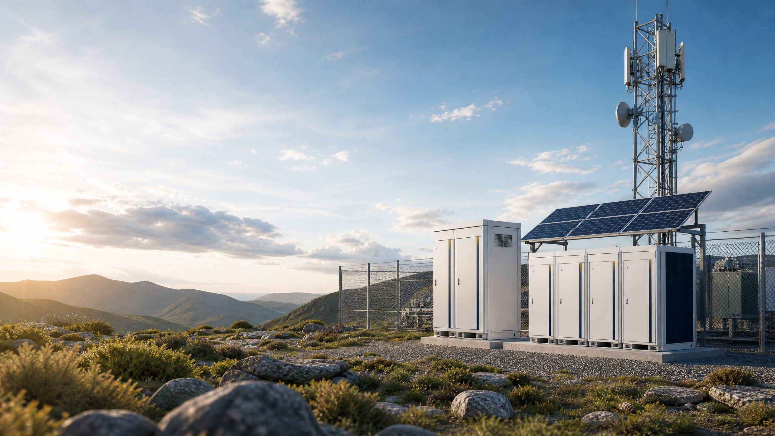
A reliable 48V telecom power system is the electrical foundation of many cellular, radio, fiber-access, and edge-network sites. It converts available AC or renewable energy into stable 48V DC telecom power, stores energy for outages, protects sensitive loads, and reports operating conditions to a remote operations team. For 5G and hard-to-reach sites, the design challenge is not simply selecting a battery. It is coordinating rectifiers, distribution, batteries, monitoring, thermal management, and service access around a clear uptime objective.
This guide explains the architecture and the commercial questions buyers should ask when comparing a conventional grid-connected system with hybrid or off-grid alternatives. It uses general engineering reasoning rather than operator-specific assumptions, because the right configuration depends on the site load profile, climate, access, backhaul equipment, autonomy target, and available energy resources.
What is a 48V telecom power system?
A 48V telecom power system is a DC power plant that normally supplies network equipment through a nominal -48V bus. The negative polarity is a long-established telecom convention, while the practical operating voltage varies with charging state and equipment design. The system typically includes an AC input, one or more hot-swappable rectifier modules, a DC distribution section, a supervisory controller, and a battery bank or telecom battery cabinet.
The rectifiers convert utility or generator AC into regulated DC. They feed the live load first and charge the batteries when spare capacity is available. During an AC interruption, the batteries support the DC bus without requiring a separate transfer event at the telecom load. When utility power returns, the rectifiers recharge the battery according to the selected charging strategy. Fuses or breakers, surge protection, disconnects, grounding, and alarms complete the power path.
The architecture is valuable because it separates the power-conversion function from the stored-energy function. A buyer can size rectifier capacity for present and expected load while sizing batteries for the desired ride-through duration. It also makes staged expansion possible, provided that the cabinet, busbars, thermal design, and protection scheme are planned for future modules.
Core components and how they work together
Rectifier system and DC distribution
A telecom rectifier system should be evaluated by more than its nominal output. Important selection questions include the number of modules, N+1 redundancy philosophy, module replacement procedure, input compatibility, efficiency across the expected load range, power-factor behavior, and controller communications. Redundancy means the plant can continue serving the load if a module is unavailable; the exact level should be matched to the criticality and maintenance model rather than assumed universally.
The DC distribution section should provide clearly identified protected feeds for radio units, transmission equipment, cooling or auxiliary loads, and other site electronics. Protection coordination matters: a downstream fault should be isolated without unnecessarily collapsing the whole bus. The layout should also leave safe access for testing and replacement.
Batteries and the telecom battery cabinet
The battery bank is the bridge between a grid failure and a service intervention. Lead-acid and lithium-based technologies can both be relevant, but the choice should reflect temperature, cycling frequency, footprint, safety procedures, expected service life, monitoring needs, and total cost of ownership. A battery cabinet may include racks, disconnects, environmental protection, battery-management electronics, and space for cable routing, but its exact construction and rating must be confirmed from the proposed product documentation.
Battery capacity is not the same as guaranteed autonomy. A practical assessment considers usable energy, discharge-rate effects, temperature, aging allowance, minimum operating voltage, conversion losses, and the load that must remain energized. Any autonomy figure should therefore be treated as a design result, not a generic product promise.
Monitoring and alarms
Remote monitoring turns a power plant from a passive enclosure into an operational asset. At minimum, the controller should make it possible to view bus voltage, load current or power, rectifier status, battery status, high- and low-voltage alarms, AC availability, temperature, and door or environmental alarms where applicable. Integration may use the site’s chosen network-management method; protocol and cybersecurity requirements should be agreed before procurement.
A useful alarm strategy distinguishes urgent loss-of-load risks from conditions that can wait for the next planned visit. Trend data can reveal battery degradation, rising site demand, repeated shallow outages, or thermal problems before they become service-affecting events.
Why 5G changes the power conversation
5G deployment can increase the importance of power design even when the radio configuration varies by site. Higher data capacity, additional active equipment, edge processing, massive-MIMO radios, and denser coverage plans can change both average consumption and peak behavior. The correct approach is to model the actual equipment bill of materials and operating modes rather than apply a single “5G multiplier.”
The site should be assessed in at least three states: normal operation, busy-hour or high-throughput operation, and outage operation. Some nonessential loads may be shed during a prolonged interruption, while priority radio and transmission loads remain live. This load hierarchy can extend effective autonomy without compromising the most important service functions.
The broader digital infrastructure context also supports disciplined energy planning. The International Energy Agency identifies data centres and data transmission networks as an emerging source of electricity demand as digitalisation expands.1 That observation does not establish a universal consumption figure for a particular telecom site, but it reinforces the need to measure real loads, plan for growth, and improve conversion and storage efficiency.
Grid-connected, hybrid, and off-grid configurations: the difference
The main difference between configurations is the role of the utility grid and the amount of local energy management required. A grid-connected plant prioritizes simplicity and dependable AC availability. A hybrid design adds solar and possibly another source to reduce generator runtime or support resilience. An off-grid plant must balance generation, storage, load, and weather uncertainty every day.
| Configuration | Primary energy source | Battery role | Strengths | Main design considerations |
|---|---|---|---|---|
| Grid-connected | Utility AC, with optional generator | Ride-through and outage autonomy | Straightforward operation and predictable recharge | Utility quality, outage duration, rectifier redundancy, battery aging, service access |
| Hybrid | Utility or generator plus PV and battery | Outage support and renewable-energy shifting | Can reduce fuel dependence and improve resilience | PV yield, charge control, seasonal weather, generator coordination, curtailment |
| Off-grid | PV and/or generator with battery storage | Daily energy balancing and backup reserve | Enables sites where grid extension is impractical | Worst-case weather, energy budget, reserve policy, generator starts, security, maintenance logistics |
A hybrid system is not automatically a smaller off-grid system. It may be designed to keep the grid as the primary source while using PV and batteries strategically. Conversely, an off-grid site must be sized against low-solar periods and equipment losses, not average sunshine alone. IEA analysis notes that storage and modernized grids can help support resilience as variable renewable energy grows.2 At a remote telecom site, that principle becomes a practical question of how much storage reserve is protected for communications continuity.
Designing remote site solar power
For remote site solar power, begin with an energy budget in watt-hours per day, not only a peak-watt rating. Record the continuous DC load, equipment duty cycles, expected growth, controller and conversion losses, battery charging losses, and any seasonal derating. Then compare the resulting requirement with a conservative solar resource estimate and a defined reserve policy.
PV can supply the daytime load and recharge the battery, while the battery covers nighttime or cloud periods. A generator, where permitted, can provide a third layer of resilience. The controls should define priorities: protect the telecom reserve, use solar when available, start supplemental generation when the reserve reaches a threshold, and avoid excessive battery cycling when conditions are unfavorable.
Physical design is equally important. Check array orientation, shading, wind exposure, lightning protection, cable voltage drop, theft deterrence, enclosure ventilation, and safe access for cleaning or inspection. At an unmanned site, remote alarms and clear local indicators are especially valuable.
Practical remote-site design checklist
Use the following checklist before requesting a system proposal:
- Define the nominal DC bus, continuous load, peak load, startup behavior, and expected five-year load growth.
- Separate critical, important, and shed-able loads for extended outages.
- Set the required autonomy target and document the assumptions behind it, including temperature and aging margins.
- Confirm AC source characteristics, generator availability, outage history, and site grounding requirements.
- Select rectifier capacity and redundancy based on present load, expansion, and maintenance conditions.
- Compare battery technologies using usable energy, operating temperature, cycling profile, safety process, and service plan.
- Specify the telecom battery cabinet environment, ingress protection needs, ventilation or cooling approach, and cable-entry arrangement.
- Define PV area, solar resource assumptions, seasonal performance, charge-control logic, and any generator interface.
- List required measurements, alarms, event logs, communications interfaces, and remote access controls.
- Review surge protection, lightning protection, overcurrent protection, isolation, labeling, and emergency procedures.
- Plan transport, lifting, installation, spare parts, firmware or controller support, and technician access.
- Establish acceptance tests for rectifier operation, battery charging, alarm reporting, load transfer behavior, and simulated outage operation.
Maintenance and lifecycle planning
Maintenance should be based on the technology and operating environment. Routine work can include visual inspection, terminal and cable checks, cabinet cleanliness, alarm review, thermal inspection, rectifier-module health checks, and verification of ventilation or cooling. Battery maintenance may include voltage and impedance or conductance trending where appropriate, management of firmware and event records, and replacement planning based on measured condition rather than age alone.
Remote monitoring reduces unnecessary visits, but it does not eliminate field inspection. A good service plan combines automated alerts with scheduled physical checks and documented escalation. For a remote site, the operator should know which alarms justify immediate travel, which can be monitored, and which spare modules or battery components are locally available.
How to compare suppliers during commercial investigation
Ask suppliers to provide a system-level design basis rather than a list of disconnected components. The proposal should explain the load assumptions, autonomy calculation, rectifier arrangement, battery usable-energy basis, environmental limits, monitoring scope, protection concept, and expansion path. It should also identify what is included in engineering, factory testing, commissioning, documentation, and after-sales support.
DAXIN ENERGY presents its business as an industrial and commercial power-solutions provider, with a telecom solution focus covering backup power, hybrid solar, and off-grid or remote sites.3 Its product portfolio also lists telecom-oriented outdoor power distribution cabinets, power-management cabinets, weatherproof cabinets, cabinets with monitoring, and solar battery storage cabinets.4 These categories are relevant starting points for a system discussion, but final voltage, capacity, enclosure, and interface details should be confirmed in the project-specific proposal.
For broader context, review DAXIN’s วิธีแก้ปัญหา and ผลิตภัณฑ์ pages. When the site load, autonomy target, and energy sources are defined, buyers can use the DAXIN contact page to request an engineering conversation without presuming that one standard configuration fits every site.
Conclusion: build resilience around the real site
A well-designed 48V telecom power system is a coordinated platform: rectifiers regulate the bus, batteries provide stored energy, distribution protects individual loads, monitoring exposes the site’s condition, and solar or generation can extend resilience where the grid is weak or absent. For 5G and remote deployments, the most important buying decision is not simply battery chemistry or cabinet appearance. It is whether the proposed architecture matches measured load behavior, outage risk, climate, access constraints, and future expansion.
The best next step is to document those inputs and compare complete system proposals on usable autonomy, maintainability, monitoring, resilience, and lifecycle practicality. DAXIN ENERGY’s telecom, cabinet, battery, and solar-storage categories provide a suitable basis for that technical discussion, while the final engineering design should remain specific to the site.
References
Image Prompt
Industrial B2B photograph of a weatherproof 48V telecom power cabinet with visible battery enclosure and solar array beside a 5G communications tower at a rugged remote site, clean engineering composition, realistic daylight, DAXIN green-and-white visual tone, no logos or readable text.