

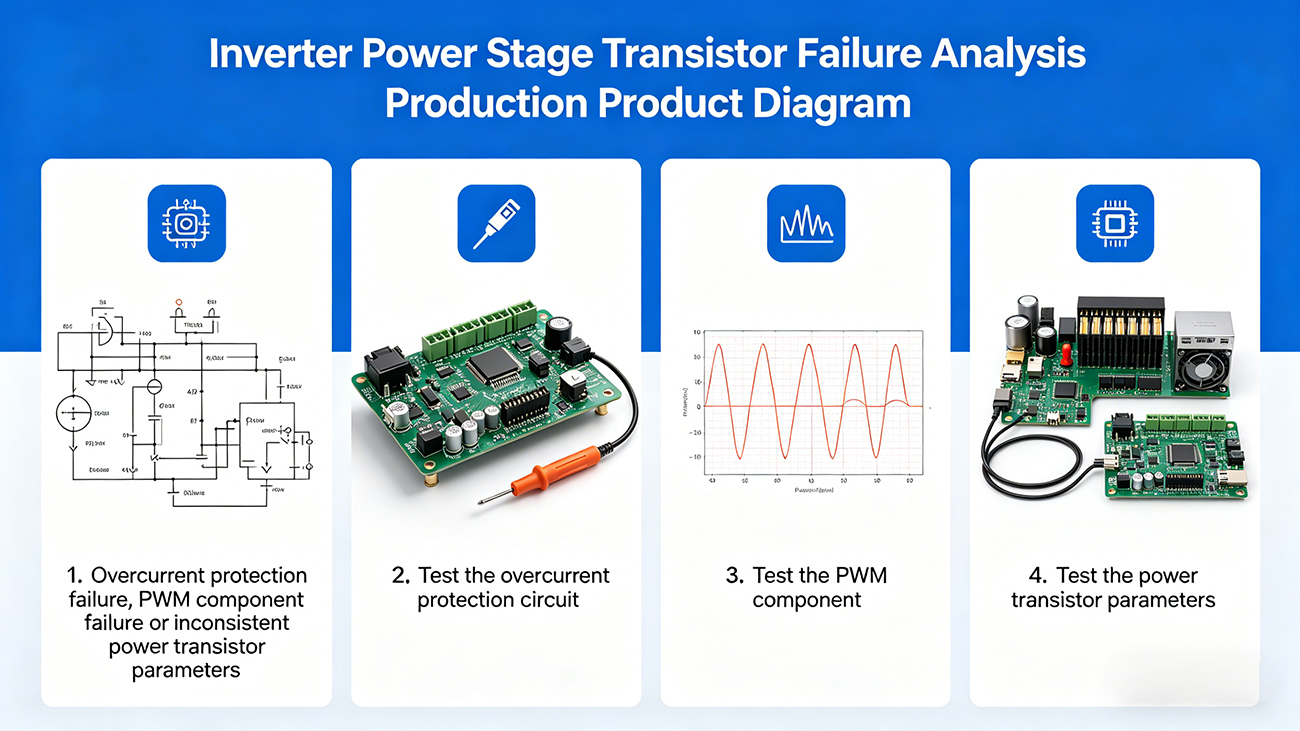
[Fault Analysis]
Based on the observed phenomenon, the issue may be caused by failure of the overcurrent protection, a fault in the PWM module, or inconsistent parameters of the power transistors.
[Diagnostic Steps]
(1) Check the overcurrent protection circuit. If it has failed, the protection circuit will not function when an overcurrent occurs at the inverter output.
(2) Check the PWM (Pulse Width Modulation) module. If faulty, the two complementary output waveforms will be asymmetric—one having a longer conduction time and the other shorter—resulting in imbalance between the two arms, or even simultaneous conduction, which can damage both transistors.
(3) Check the parameters of the power transistors. If there is a large mismatch, even with symmetrical input waveforms, the output will become asymmetrical. This waveform passes through the output transformer, causing magnetic bias (flux imbalance). Over time, this leads to transformer saturation and a sharp rise in current, burning out the transistors. Once one transistor fails, the other will also fail subsequently.
Leave a Reply